Hot Bar Reflow Soldering Slideshow
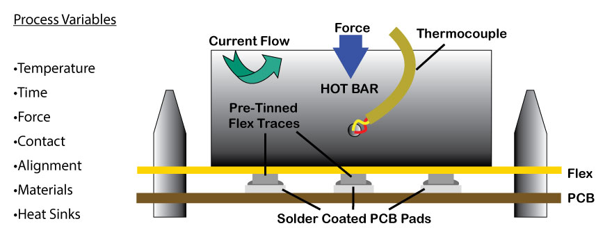
SOLDERING PROCESS
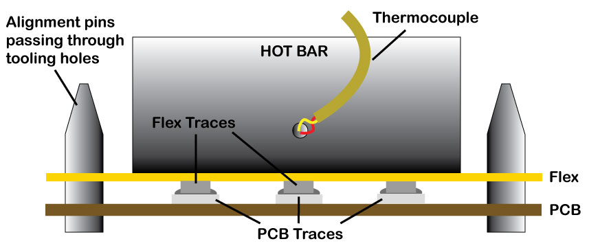
- A Thermode is used to apply heat and pressure over a specific time/temperature profile. Temperature feedback is provided via thermocouple.
- Solder needs to be heated to at least 40 degrees Celsius above melting point for about 2-3 seconds to provide the best wetting and flow.
- Heat is produced by passing an electrical current through a thermode which is resistive.
- The force applied transfers the heat to the part and the solder.
- Flux is used to remove and prevent oxide formation.
THERMODE MAINTENANCE
- Routinely remove flux and polyimide residue from thermode using Acetone or Isopropyl Alcohol.
- Resurface thermode face with 600 grit silicon carbide paper on flat surface at low force or grinding wheel if sufficient material is present.
- Improper maintenance in cleaning and resurfacing can result in damaged thermovouples and unlevel thermode faces.
- Use interlayer to reduce contamination of the thermode.
- Automatic Kapton feeder can auto-advance between bonds.
- Permacel P-440 Tape can be applied to thermode face and routinely changed.
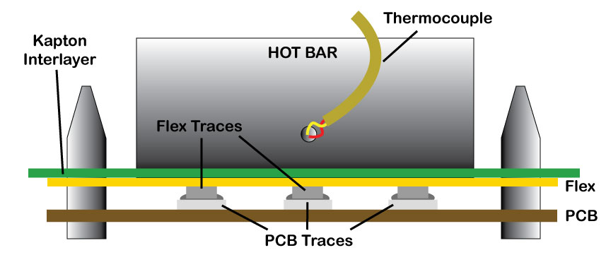
Thermocouple Function
A thermocouple is two wires of dissimilar alloy that are joined into a ball at one end, and open at the other end. Typically the open end is fitted with a plug and the ball end is welded to the thermode near the tip. As thermode temperature increases, so does the voltage across the two wires. This changing voltage feeds back a temperature reading, telling the power supply the temperature of the thermode face. This is what allows the power supply to accurately control the thermode temperature.

Thermocouple Types
Type E: Chromel-Constantan
Type J: Iron-Constantan
Type K: Chromel-Alumel
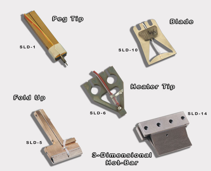
THERMODE TYPES
PCB Design
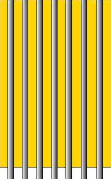
- Width of the PCB traces should be 50% of the pitch to avoid short circuits
- Make PCB traces wider than flex traces to allow solder to flow and fillets to form
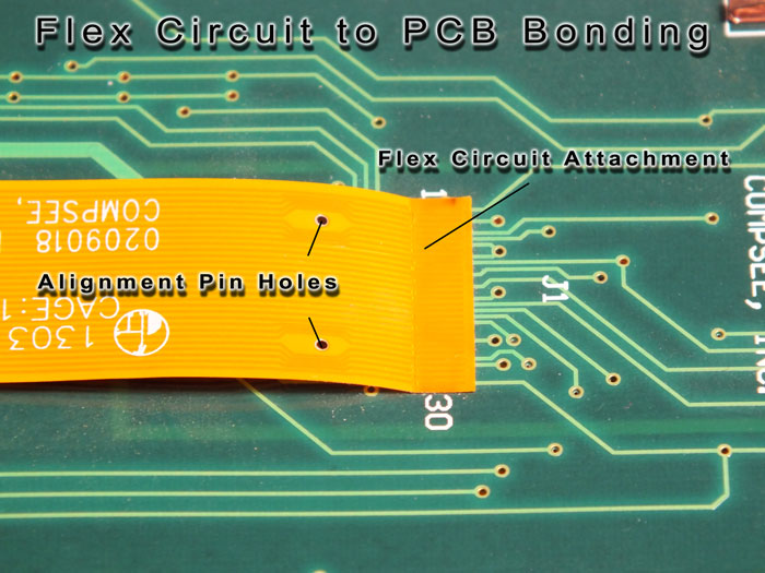
- Tooling holes in PCB and Flex allow easy alignment of traces
- Provide room for thermode to overhang both ends of pad area by 0.040”(1mm)
PROBLEM
Differences in heat sinking from pad to pad can cause uneven heating:
Unequal trace area and plated through holes act as a heat sink, causing uneven heat distribution.

SOLUTION
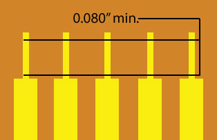
Equal trace sizes (mass) leads to equal heating and better solder joint quality. Minimum .08" wide solder area is recommended.
Flex Circuits
- Most common type is polyimide (also known under the trade name of Kapton)
- Two layers of polyimide encapsulate the copper traces(normally 0.5–2oz)
- Copper is Rolled Annealed or Electro-Deposited (most cos teffective and widely used)
- Thickness of copper traces ranges from 0.0007–0.004 inches (18-100microns)
- Operating temperatures ranging from130–200°C (can with stand soldering temperatures up to 300°C for a short time)
- Thickness of the polyimide ranges from 0.001–0.0047inches (25-120microns)
| Type | Advantages | Disadvantages | |||
|
|
Lower thermode temperatures. | Flux contamination on thermode. Leads can be damaged or bent when handled. | 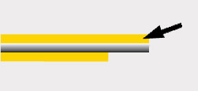
|
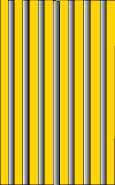
Maximum polyimide thickness, the top layer, needs to be .002 inches or 50 microns. Loss (thermal barrier) of 60–80°C per 25 microns thickness |
|
Single Sided | Easy to handle. Minimal flux contamination on thermode. | Higher thermode temperatures due to thermal barrier. | 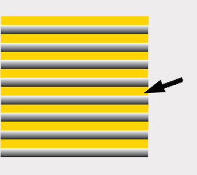
|
Minimum pitch needs to be.008 inches or 200 microns to avoid short circuits. |
|
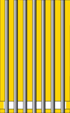
Open Windowed | Lower thermode temperatures. | Flux contamination on thermode. Part alignment is critical. | 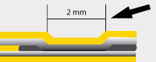
|
Minimum pad length needs to be .080 inches or 2 mm to allow fillets to form. |
Flux
- Flux is a chemical agent that assists in the soldering process by removing and preventing oxide formation.
- Flux is a catalyst that does not become part of the final metal composition.
- Flux improves the wetting action of solder by lowering the surface tension of the solder.
- Each flux has an optimum working temperature where it reacts chemically with oxidized metal surfaces
Flux activation or working temperature is an optimum range of temperatures where it chemically reacts with oxidized metal surfaces.
Flux for electronics applications:
- Must be heated to remove oxides
- Relatively “inert” at room temperatures
Electronics Fluxes
Water Soluble
- Most active type of flux
- Residue is corrosive and conductive
- Requires cleaning equipment and hot water treatment
Rosin Activated
- Very active flux
- Requires saponifier (chemical) and hot water to clean
Rosin Mildly Activated
- Promotes good wetting on oxidized surfaces
- Requires saponifier (chemical) and hot water to clean
No Clean
- Least active type of flux
- Reflow process must occur within 5 minutes of application
- Low solids content leaves little residue
- No cleaning required or possible
Eutectic solder increases process predictability
-Melting point of the solder
-Flow (wetting) action behavior
Eutectic solders
–Transitions from solid to liquid at a fixed temperature
–Lower melting point than parent metals
•Example: Sn63Pb37 melts at 183 C
•Example: Sn62Pb36Ag2 melts at 179 C
Selecting Solder Alloys
Solder alloys are selected for the following properties:
•Melting point
•Mechanical characteristics
•Wettability
•Abscence of Lead
About Solder
•Common solder alloys used in electronics manufacturing:
–tin-lead:Sn63Pb37 (Melting Point 183 Celsius)
–tin-silver-copper:SAC305: Sn96.5Ag3Cu0.5 (Melting Point 218 Celsius)
–tin-silver-copper:SAC305: Sn96.5Ag3Cu0.5 (Melting Point 218 Celsius)
•Alternative “lead free” alloys include:
–tin-silverSn96Ag4 (Melting Point 221 Celsius)
–tin-copper-nickelSn100C (Melting Point 227 Celsius)
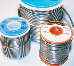
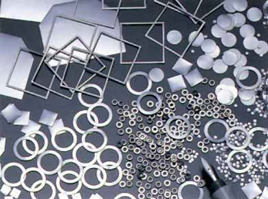
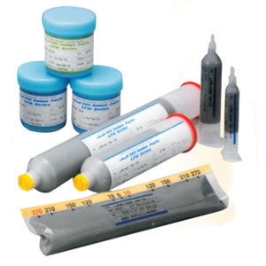
Physical Forms of Solder
•Rosin Core Wire Solder (various sizes and flux types)
•Pre-Forms (custom manufactured)
•Solder Paste (spherical metal particles suspended in flux)